Introduction
Advanced driver assistance systems rely heavily on accurate data from cameras and LiDAR (Light Detection and Ranging) sensors. These devices must be precisely aligned to interpret lane markings, detect obstacles and measure distances. Even minor misalignment can lead to false warnings or degraded performance. Understanding how to calibrate camera and LiDAR sensors correctly is essential for technicians who service ADAS-equipped vehicles.
Sensor Differences and Why Calibration Matters
Cameras capture images of the road to identify lane lines, traffic signs and vehicles. LiDAR sensors emit laser pulses and measure the reflected light to build a detailed 3D map of surroundings. While both sensors contribute to tasks like lane keeping and adaptive cruise control, they process different types of data. Calibration ensures each sensor’s coordinate system aligns with the vehicle’s centerline and other sensors so that sensor fusion systems can accurately interpret the environment.
Calibration is required when sensors are replaced, windshields or bumpers are removed, suspension components are adjusted or after collisions. Environmental factors such as heavy vibration, potholes or strong impacts can also shift sensor positions over time.
Camera Calibration Basics
Most camera systems require either a static calibration performed in a workshop or a dynamic calibration carried out during a test drive. The procedure varies by manufacturer, but common steps include:
- Preparation
- Verify tyre pressures and ride height to ensure correct vehicle stance.
- Remove any objects from the dashboard and ensure the windscreen is clean.
- Position the vehicle on a level surface and lock the steering wheel straight ahead.
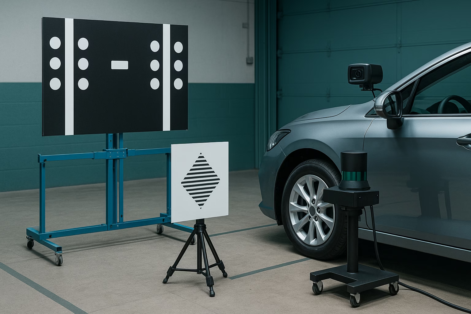
- Target Placement
- Set up calibration targets at specified distances and heights relative to the vehicle. Targets may include chessboard patterns, dot matrices or barcodes, depending on the system.
- Use measuring tools to ensure the target is square to the vehicle centerline. Misalignment here will result in inaccurate calibration.
- Connecting the Scan Tool
- Use an approved diagnostic tool to initiate camera calibration. The tool guides the technician through test sequences and verifies that the camera correctly identifies the target.
- For dynamic calibrations, follow the on‑screen instructions to drive the vehicle at a specified speed on a road with clear lane markings until the system completes alignment.
- Verification
- Once calibration is complete, clear any stored codes and test the lane keeping or road sign recognition functions on a controlled drive.
- Record calibration data and confirm there are no warnings on the dashboard.
LiDAR Calibration Basics
LiDAR sensors often mount behind fascias or within grills. Calibration focuses on ensuring the sensor’s aim and vertical and horizontal angles are within specification.
- Inspection and Preparation
- Inspect the sensor housing for cracks or misalignment. Even minor bumper damage can affect aim.
- Ensure the fascia in front of the sensor is clean and free of stickers, as any obstruction can scatter or absorb laser pulses.
- Alignment Procedure
- Position the vehicle in front of a special reflector panel or calibration target provided by the manufacturer.
- Some systems use built‑in alignment modes accessed via scan tool. The tool projects a virtual horizon or grid onto the LiDAR’s field of view and guides the technician to adjust mounting screws until the sensor aligns with reference marks.
- Verify rotational alignment (yaw) as well as vertical angle (pitch) and lateral displacement (roll).
- Software Calibration
- Once physically aligned, use the diagnostic tool to perform software calibration. This step records the sensor’s orientation and stores calibration values in the control module.
- Clear any related fault codes and test the system by driving in an environment where LiDAR can detect fixed objects like walls or parked cars.
Tools and Best Practices
- Dedicated calibration frames and targets – Invest in manufacturer‑approved targets to ensure accuracy.
- Precision measuring tools – Digital levels, tape measures and plumb bobs help set up targets accurately.
- Clean, level workspace – A flat surface and good lighting are critical to reliable calibrations.
- Documentation – Record pre‑ and post‑calibration data, including target distances, ambient temperature and any fault codes.
- Training – Stay up‑to‑date with each manufacturer’s latest procedures. Camera and LiDAR technology evolves quickly.
Common Pitfalls to Avoid
- Skipping ride-height checks – Suspension modifications or worn springs can alter camera angles. Verify ride height before calibrating.
- Ignoring lighting conditions – For static camera calibrations, ensure consistent ambient light; glare or dark spots may prevent the camera from reading targets correctly.
- Improvised targets – DIY patterns printed on paper often lack the precision required. Use certified targets.
- Incomplete calibrations – If a test drive is part of the procedure, do not short-circuit the process. Incomplete dynamic calibration may leave systems partially aligned.
Summary
Accurate calibration of camera and LiDAR sensors is fundamental to safe ADAS operation. By understanding the differences between sensors and following manufacturer guidelines for both static and dynamic procedures, technicians can ensure that vehicles interpret their surroundings correctly. A clean, level workspace, proper targets and precise measurements are indispensable tools. With attention to detail and ongoing training, camera and LiDAR calibrations can be performed efficiently and reliably.

Hiran Alwis is an automotive lecturer and ADAS specialist with over 15 years of experience in diagnostics, advanced safety systems, and technical training. He founded ADAS Project to help everyday drivers and workshop technicians understand and safely use advanced driver assistance systems.