Introduction
Radar sensors are the backbone of advanced driver assistance functions such as adaptive cruise control (ACC), automatic emergency braking and blind spot monitoring. These sensors emit radio waves and interpret reflections to judge distances and speeds of objects. For these systems to work reliably, radar modules must be accurately calibrated. Misaligned radar can lead to late braking, unnecessary warnings or, worse, collisions. This article outlines best practices for calibrating radar sensors in an ADAS environment.
When Radar Needs Calibration
Several scenarios warrant radar calibration:
- After collisions or minor impacts – Even small knocks to the bumper can shift the radar’s aim.
- After front-end repairs – Bumper replacements, grille repairs or adjustments to the vehicle frame can misalign sensors.
- Replacing or reinstalling the radar module – New or refurbished units must be programmed and aligned.
- Modifying ride height – Changes in suspension (new springs, leveling kits) alter the radar’s angle relative to the road.
- Software updates – Some updates require recalibration to reset baselines.
Failing to calibrate can result in erroneous readings or inoperative driver assistance features.
Equipment Needed
A proper calibration setup includes:
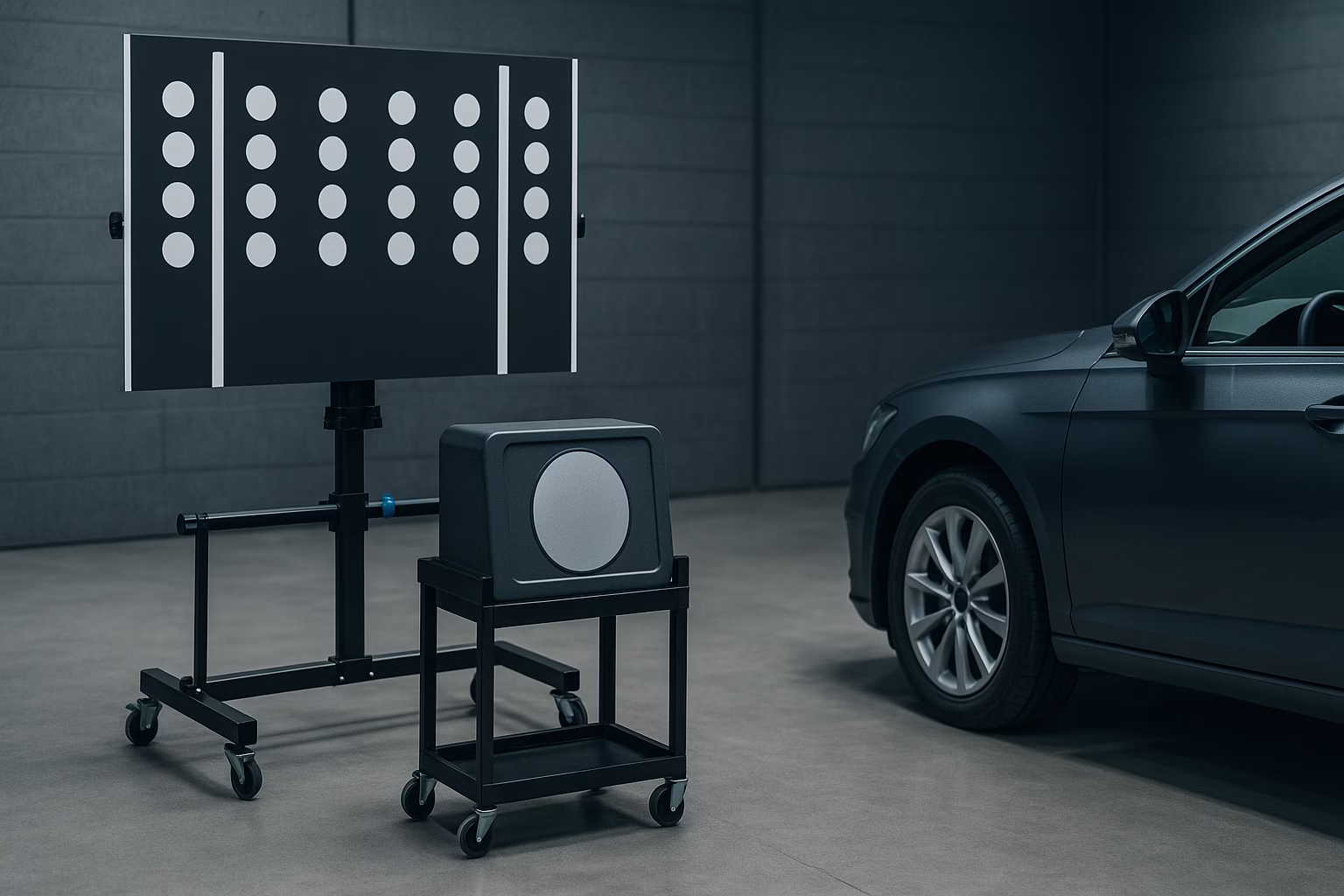
- Radar target board – A large, reflective panel with a specific pattern that the radar senses during calibration.
- Adjustable stand or frame – Allows precise positioning of the target board.
- Calibration fixture – Some systems use a “corner reflector” to mimic radar reflections at defined distances.
- Measuring tools – Tape measures, levels and plumb lines to set correct target distance and height.
- Diagnostic scan tool – Initiates calibration sequences and programs the radar module.
Invest in manufacturer‑approved equipment because radar frequencies and target patterns vary by brand.
Preparing the Vehicle and Workspace
- Choose a level surface – Radar alignment depends on pitch and yaw; an uneven floor can introduce errors.
- Check tyre pressures and ride height – Uneven pressures can tilt the vehicle.
- Ensure sensor cleanliness – Remove dirt, ice or paint overspray from radar covers.
- Avoid metallic interference – Metal racks, large tools or overhead beams near the target board can distort radar reflections.
- Control lighting – Although radar operates with radio waves, consistent workshop lighting helps you read measurement scales and see alignment marks.
Alignment Procedure
- Position the vehicle – Park with wheels straight ahead and steering locked. Many manufacturers specify a precise distance from the front axle to the target board.
- Set up the target – Use measuring tools to center the board on the vehicle’s longitudinal axis. Adjust height to match the sensor’s reference point, often measured from the ground to a designated mark on the bumper.
- Check orientation – Use a level to ensure the target is perpendicular to the vehicle. Even a slight tilt can cause the radar beam to deflect.
- Initiate calibration – Connect the scan tool and follow on‑screen instructions. Calibration modes may take a few minutes as the radar “learns” reflections from the target.
- Adjust as needed – Some systems allow fine tuning of the sensor’s aim via mechanical adjustments or within software. Follow prompts to tweak yaw or pitch until the scan tool confirms alignment.
Post-Calibration Verification
After calibration, perform a functional test drive. Verify that adaptive cruise control maintains proper distance and that collision warnings trigger at appropriate times. In some cases, the system may require a dynamic test drive at specified speeds to confirm alignment. Watch for unusual warnings or error messages.
Troubleshooting Common Issues
- Persistent misalignment codes – Double-check measurement distances and ensure the vehicle is on level ground. Inspect mounting brackets for damage.
- False positives (ghost objects) – Check for metallic objects near the sensor or target. Sometimes removal and reseating of the module resolves internal reflections.
- No response from sensor – Ensure power and communication lines are connected. A blown fuse or faulty harness can mimic misalignment.
- Intermittent warnings – Environmental factors like heavy rain, snow or thick dirt on the radar cover can affect performance. Clean surfaces and retest.
Summary
Radar calibration is crucial for the reliability of driver assistance features. Proper alignment involves more than simply fitting a new sensor; it requires precise measurement, the right equipment and adherence to manufacturer procedures. By preparing a clean, level workspace, positioning targets accurately and verifying results through test drives, technicians can ensure radar systems perform as intended. Consistent attention to best practices protects drivers and helps your workshop maintain high standards of safety and professionalism.

Hiran Alwis is an automotive lecturer and ADAS specialist with over 15 years of experience in diagnostics, advanced safety systems, and technical training. He founded ADAS Project to help everyday drivers and workshop technicians understand and safely use advanced driver assistance systems.