Light detection and ranging (LiDAR) is becoming a key sensor in the latest generation of ADAS and automated driving systems. Unlike cameras, which capture a two‑dimensional colour image, or radar units that emit radio waves to measure distance and velocity, LiDAR projects pulses of light and measures the time it takes for them to reflect back. By scanning tens of thousands of points per second, a LiDAR sensor builds a detailed 3D point cloud of the surrounding environment. This rich data set can identify the shape and position of vehicles, pedestrians and roadside structures with high precision.
From a calibration perspective, LiDAR presents different challenges compared to camera and radar setups. Cameras require both intrinsic calibration (to correct lens distortion) and extrinsic calibration (to align the camera’s coordinate system with the vehicle’s coordinate frame). This is typically done by positioning the vehicle relative to a printed target board and using software to analyse the image. Radars, on the other hand, emit microwaves and measure Doppler shift; calibration often involves aiming the sensor at a specially designed radar reflector or plate at a prescribed height and distance. Adjustments are made via physical shims or built‑in screws until the radar’s beam aligns with the vehicle axis.
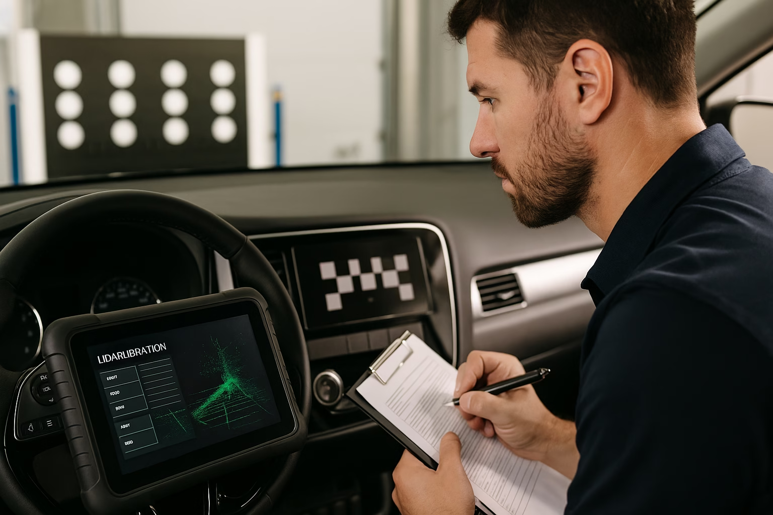
LiDAR calibration focuses primarily on extrinsic alignment and sensor health. Because LiDAR sensors use dozens of laser channels arranged vertically, it is critical that the unit is mounted at the correct pitch, roll and yaw. If the sensor is even a degree off, the point cloud will skew, leading to inaccurate object recognition and range estimates. Calibration typically involves placing reflective targets or poles at known positions around the vehicle and running a diagnostic routine that compares the measured point cloud to the expected geometry. Some OEMs provide calibration fixtures that hold corner cube reflectors or 3D panels at specific distances, while others require driving the vehicle along a straight path lined with reflective markers. The software then computes the sensor’s mounting offset and applies corrections.
Another difference is that LiDAR sensors may require periodic internal calibration of their laser channels. Over time, the timing circuits that measure the time of flight can drift, affecting range accuracy. Some sensors include a built‑in reference target or calibration board that the scanner periodically sweeps during startup to self‑calibrate. Others rely on service tools to evaluate each channel and adjust timing parameters. Technicians performing LiDAR calibration must follow the manufacturer’s procedure, which often includes cleaning the sensor window, verifying firmware versions and ensuring that the vehicle sits at the correct ride height and tyre pressures. Because LiDAR data is used in conjunction with camera and radar inputs, it is also important that all sensors share a common coordinate reference; this might require a multi‑sensor calibration process after major repairs.
Environmental factors have a significant impact on LiDAR calibration. Dust, dirt and insect splatter on the sensor window can attenuate the laser pulses and introduce noise into the point cloud. Even a thin layer of condensation or protective film can shift the timing by fractions of a nanosecond, which translates to centimetres of range error. Technicians must clean the sensor with appropriate materials and inspect for cracks or chips. Additionally, because LiDAR uses near‑infrared light, ambient infrared sources such as sunlight or halogen lamps can interfere during calibration. Most procedures call for an indoor workshop with controlled lighting or a shaded outdoor area. Temperatures should also be within a specified range to prevent thermal drift in the sensor electronics.
In contrast, radar calibration is less affected by lighting but can be sensitive to metallic objects in the test area. Radar reflectors must be placed far enough from walls and floor to avoid multipath reflections. Similarly, camera calibration boards must be evenly lit and free of glare, but they do not require the dark room conditions of LiDAR. Recognising these differences helps technicians prepare the workspace accordingly. For example, a shop might invest in dedicated LiDAR calibration bays with matt black walls and minimal reflective surfaces, while using a separate area with bright, uniform illumination for camera targets.
Another key distinction is the availability of calibration routines. Many automotive cameras and radars support both static and dynamic calibration, where dynamic procedures involve driving the vehicle while the system learns the road environment. LiDAR calibration is almost always static because the sensor generates a complete 3D map without needing motion. However, some manufacturers require a short road test after the static calibration to confirm sensor fusion performance and to ensure that the corrected point cloud aligns with map data. Technicians should pay attention to post‑calibration verification steps such as fault code checks, live data inspection and test drives with known objects to confirm detection ranges.
As LiDAR technology proliferates from high‑end vehicles to mass‑market models, calibration equipment and training will need to keep pace. At present, only a handful of third‑party alignment rigs are available, and many OEMs restrict LiDAR calibration to authorised repairers. Investing in the correct tools is crucial because improvising with camera boards or radar plates will not yield accurate results. Workshops should also monitor software updates, as LiDAR calibration routines may change with firmware revisions or new point‑cloud processing algorithms. Detailed documentation – including photos of target placement, recorded offset values and environmental conditions – provides proof of compliance for insurers and helps diagnose any post‑repair issues.
In summary, calibrating a LiDAR sensor shares some high‑level similarities with camera and radar setups – all involve aligning the sensor to the vehicle and verifying its output – but the methods and sensitivities differ substantially. LiDAR demands precise mechanical alignment, reflective 3D targets, clean and controlled environments, and sometimes internal channel calibration. Technicians who understand these nuances and follow the OEM procedures can ensure that LiDAR‑equipped vehicles perceive the world accurately, enabling advanced driver assistance features to operate reliably alongside radar and camera inputs. Ignoring these requirements risks degraded performance, warning lights and potential liability if an accident occurs due to sensor misalignment.

Hiran Alwis is an automotive lecturer and ADAS specialist with over 15 years of experience in diagnostics, advanced safety systems, and technical training. He founded ADAS Project to help everyday drivers and workshop technicians understand and safely use advanced driver assistance systems.